
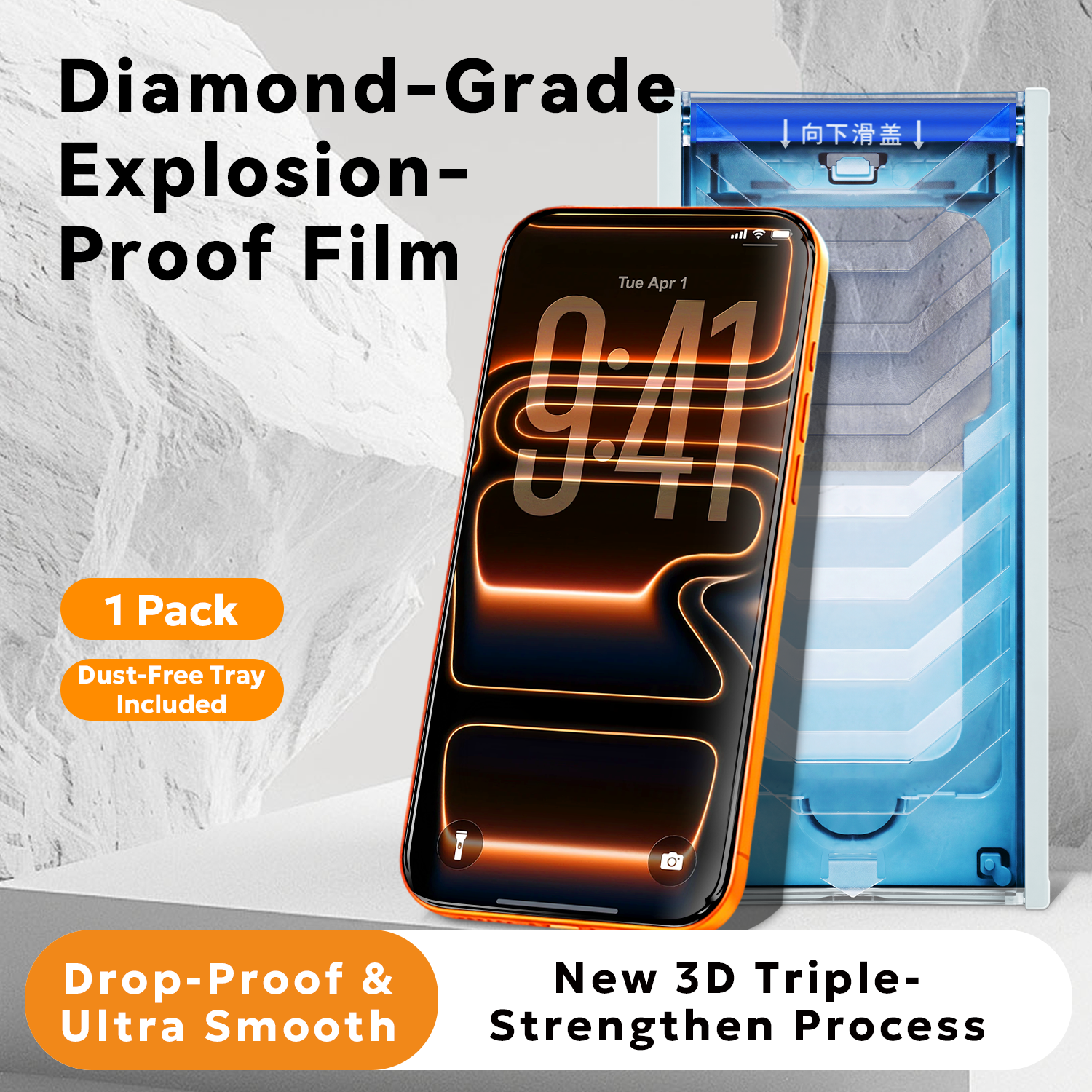
An engineering guide to shatter-resistant screen films — fracture mechanics, high alumina glass, ion exchange strengthening, edge reinforcement, fragment retention, and the test battery that proves it
Most screen films fail the same way: not in the middle, but at the edge. A phone lands corner-first, the glass chips, and a crack that started as a 0.3 mm nick travels across the display in under a second. An anti-shatter film is engineered around that reality. It is not simply "harder glass" — it is a system of substrate chemistry, built-in compressive stress, edge geometry, and bond-line design that together decide whether impact energy is absorbed or converted into flying fragments. This article explains the mechanics behind shatter-resistant film, how high alumina glass and chemical strengthening change fracture behaviour, why edge processing is a safety specification rather than a cosmetic one, and how B2B buyers should validate shatter performance in 2026.
1. What "Anti-shatter" Actually Means
"Anti-shatter" is one of the most loosely used terms in mobile accessories, so it is worth defining precisely. A shatter-resistant film is a tempered glass screen film designed so that, when it does break, it breaks into small, blunt, tightly held granules instead of long sharp shards, and so that the break is far less likely to initiate in the first place. Two distinct properties are bundled under one marketing term:
The probability that a given impact will NOT crack the glass. Driven by substrate chemistry, surface compressive stress, edge quality, and thickness. This is the part buyers usually mean by "stronger".
What happens once the crack has already run. Fragment size, fragment sharpness, and whether the pieces stay bonded to the carrier film or separate and fall away. This is the part that determines injury risk and complaint rates.
A film that is strong but fragments badly is still a liability; a film that fragments safely but chips easily will generate warranty returns anyway. Production-grade shatter protection requires both.
| Model | TR-020 |
| Material | High Alumina Glass |
| Thickness | 0.33 mm |
| Surface Hardness | 9H |
| Edge Process | 3D hot bending |
| Features | Explosion-proof, scratch resistant, anti-chip, oleophobic coating |
| Application | Smartphone screen protector |
| Brand | TENWINGLASS |
| Key Characteristics | Diamond-grade shatterproof film, high alumina glass, 3D hot bending, full screen coverage, anti-fingerprint |
Every specification in that table exists for a mechanical reason, and the rest of this article works through them one by one. The distinction that matters most is the substrate: high alumina glass is not the same material as the soda-lime glass used in commodity protectors, and the difference shows up directly in fracture behaviour.
2. Why Glass Breaks: The Mechanics Behind a Shattered Screen
Glass is not weak — it is brittle. In its ideal, flaw-free state, glass has a theoretical strength approaching 10 GPa, far higher than steel. Real glass never reaches that figure because strength is limited by microscopic surface flaws, a principle formalised by Griffith in 1920: fracture stress is inversely proportional to the square root of the largest flaw present. Halve the flaw size and you roughly increase breaking stress by 40%.
Three consequences follow directly, and all three shape how a shatter-resistant film is designed:
| Mechanism | What It Means Physically | Design Response |
|---|---|---|
| Stress concentration at flaws | At the tip of a crack, stress multiplies by roughly 2 × √(a/ρ), where a is crack length and ρ the tip radius. A sharp flaw concentrates stress hundreds of times over. | Blunt or eliminate surface flaws; polish edges to remove micro-cracks |
| Subcritical crack growth | Under sustained stress and humidity, cracks creep forward at stresses well below the critical value. A chip that appears benign on Monday can become a full crack by Friday. | Compressive surface stress closes crack mouths; moisture-resistant coatings |
| Edge-origin initiation | Cut and ground edges carry far denser flaw populations than the fire-polished faces. Industry experience places the majority of field breakages as originating at the edge or a corner. | Dedicated edge grinding, polishing, and edge-strengthening steps |
This is why "just use thicker glass" is a poor answer to shatter protection. Thickness raises bending stiffness and improves load distribution, but it does nothing about the flaw population that actually starts the crack. Strength comes from the surface and the edge, not from bulk mass.
3. Tempered Glass: Pre-Loaded Stress as a Defence
Tempered glass works by deliberately trapping stress inside the material. During chemical strengthening, the outer surface is put into high compression while the interior sits in tension. Because cracks only propagate under tension, a crack attempting to open at the surface must first overcome the compressive layer — which requires far more energy than an untreated surface does.
That internal stress field also governs post-break behaviour. When a tempered sheet finally fails, the stored elastic energy releases all at once and the glass disintegrates into a dense pattern of small blunt granules rather than long, needle-like shards. The fracture pattern is a direct consequence of the stress profile, not of any additive or coating. Two parameters define the profile:
The magnitude of surface compression, quoted in MPa. Higher CS means a greater load is needed to open a surface crack, so resistance to scratching, bending, and initiation improves. Typical production values for chemically strengthened screen glass fall in the 600–900 MPa band.
How deep the compressive layer extends, quoted in micrometres. A shallow layer resists fine scratches but does little against a real impact; a deeper layer resists blunt impact but must not be pushed so far that the part becomes self-destructive. Typical range is 35–50 µm.
CS and DOL must be balanced, and they interact with thickness. A thin film with very high CS and very deep DOL stores so much internal energy that it may fail spontaneously or shatter violently on contact. This is the reason a 0.33 mm shatter film is not simply a 0.26 mm optical film with the strengthening dialled up — the whole profile is re-optimised for impact rather than for transmittance.
4. High Alumina Glass vs Soda-Lime: A Substrate Comparison
The single most consequential material choice in a shatter-resistant film is alumina content. Standard soda-lime float glass is cheap, widely available, and adequate for a basic protector. Increasing the alumina (Al2O3) fraction in the glass network raises the modulus, raises the achievable compressive stress, and improves the depth to which strengthening can be driven — all of which translate into better impact performance.
| Property | Soda-Lime Glass | High Alumina Glass | Aluminosilicate (premium) |
|---|---|---|---|
| Al2O3 content | ~1–2% | ~15–20% | ~18–25% |
| Young's modulus | ~72 GPa | ~78–82 GPa | ~80–84 GPa |
| Achievable CS | 450–650 MPa | 650–850 MPa | 800–900+ MPa |
| Achievable DOL | 8–15 µm | 30–45 µm | 40–55 µm |
| Relative impact performance | Baseline | Substantially higher | Highest |
| Relative cost | Lowest | Moderate | Highest |
The practical reading of the table: high alumina glass is what makes a genuinely shatter-resistant film possible at a mass-market price point. It is the enabling material behind the TR-020 specification above, and it is the reason a 0.33 mm high-alumina part can outperform a thicker soda-lime part on impact while remaining thin enough for full-screen coverage.
5. Ion Exchange: How Strength Is Put Into the Glass
Chemical strengthening is a substitution reaction. Cut glass parts are immersed in a bath of molten potassium nitrate at elevated temperature. The bath is rich in potassium ions; the glass surface is rich in sodium ions. Because the two species are chemically similar but different in size, sodium ions diffuse out of the glass and are replaced by larger potassium ions from the bath.
A potassium ion occupies roughly 30–40% more volume than the sodium ion it replaces. Physically wedging a larger ion into a fixed lattice position forces the surrounding network into compression — the glass is, in effect, squeezing itself. This is the origin of the CS and DOL figures discussed earlier, and it is why the process is sensitive to tight control:
| Process Parameter | Typical Range | Effect If Out of Control |
|---|---|---|
| Bath temperature | 380–450 °C | Too cool: insufficient exchange. Too hot: stress relaxation, warping, loss of flatness |
| Immersion time | 2–8 hours | Short: shallow DOL, poor impact resistance. Long: excessive stored energy |
| Bath purity | Controlled Na/K ratio | Sodium build-up in the bath suppresses exchange and lowers CS batch to batch |
| Pre-clean quality | Flaw-free, contamination-free surface | Residue masks the surface; ions cannot exchange uniformly |
| Post-process verification | Surface stress meter (FSM) | Without measurement the CS/DOL claim is unverifiable — always ask for the readings |
Non-destructive verification uses an optical surface stress meter, which reads the birefringence induced by stress in the strengthened layer and reports CS and DOL directly. For a buyer, batch-level CS/DOL readings — not a single nominal figure on a datasheet — are the minimum evidence that strengthening was actually performed rather than skipped.
6. The Edge Is the Weak Point — and 3D Hot Bending Is a Safety Feature
Because fracture almost always initiates at an edge or corner, edge processing sits at the centre of shatter engineering. A raw cut edge is effectively a row of microscopic flaws; grinding and polishing blunt those flaws and remove the damaged zone. Edge quality can be graded in practical terms:
| Edge Type | Geometry | Impact Behaviour |
|---|---|---|
| Raw cut | Sharp 90° edge, visible micro-chipping | Poor. Chips on light contact; crack initiates immediately |
| 2.5D | Ground and polished bevel / round edge | Good for flat displays. Comfortable swipe; reduced chipping |
| 3D hot bent | Curved over a mould to match the device contour | Best. Full bond to the display edge, no lifting lip to catch impact |
The 3D hot bending process forms the glass at 650–750 °C over a shaped mould, which matters for shatter performance for a reason that is often overlooked: a flat film fitted to a curved display leaves an unbonded lip at the edge. That lip does three harmful things — it becomes the first point of contact in a corner impact, it collects dust that acts as an abrasive, and it creates a stress riser where the film flexes freely against a bonded region. Dimensional control of the bend, typically held within ±0.05 mm, is what allows the film to sit flush and share impact load with the display rather than absorb it alone.
For a fuller picture of how these steps run in production, the production steps walkthrough follows the sequence from cutting through to final inspection.
7. Fragment Retention: What Happens After the Glass Breaks
The word "explosion-proof" in product literature describes post-breakage behaviour. Fully tempered glass, when it fails, releases its stored stress and divides into a dense field of compact granules. Compared with annealed glass — which separates into long, sharp, dagger-like shards — the tempered pattern drastically reduces laceration risk.
Fragment behaviour is governed by the stress profile and the bond line, and the two are specified together:
Higher stored stress yields a finer granule count per unit area. Fragment counts are routinely measured over a defined square and compared against a reference pattern — a coarse, uneven break pattern indicates incomplete strengthening.
A silicone or OCA bond line that grips the fragments keeps the assembly together as one piece. This is what prevents granules from migrating into a pocket, an eye, or a device's speaker mesh.
The film is a sacrificial layer. In a successful outcome the film shatters, the display survives, and the user replaces a low-cost accessory instead of a device module — which is the entire economic argument for the product.
This is why shatter performance cannot be validated by a static hardness number. A 9H surface tells you the coating resists scratches; it tells you nothing about fragment count or adhesive retention after breakage. The two must be tested separately.
8. Hardness, Anti-Chip and the Oleophobic Layer
The remaining specifications on the datasheet address the everyday damage that precedes a real break. Each has a concrete meaning:
| Specification | What It Governs | How It Is Verified |
|---|---|---|
| 9H pencil hardness | Resistance to fine abrasion — keys, coins, grit in a pocket | ASTM D3363 pencil test; no visible scratch at 9H |
| Anti-chip edge | Resistance to corner impact damage — the most common initiation event | Corner drop and edge impact fixtures; micro-bevel inspection |
| Oleophobic coating | Fingerprint, oil and smudge resistance; swipe smoothness | Contact angle measurement; reciprocating wipe cycles |
| Explosion-proof structure | Fragment retention and safe failure mode | Controlled break test; fragment count and adhesion check |
| Full screen coverage | No exposed display edge; no unbonded lip to catch impacts | Contour gauge against the target device; fit sample approval |
The oleophobic layer deserves particular attention because it is the first property to degrade in service. Hydrophobic and oleophobic performance is defined by the contact angle of a water droplet: a fresh coating commonly measures above 110°, and the rate at which that angle falls under repeated wiping is the real durability metric. A coating that starts high but collapses after a few thousand wipes disappoints users long before the glass itself is damaged. If you need the wider context of how hardness, edge geometry and coating grades compare across film types, our guide to 9H hardness and 2.5D edge design works through the same specifications in more detail.
9. The Test Battery That Proves Shatter Performance
A shatter claim is only as good as the test behind it. Impact performance is notoriously easy to overstate because results depend heavily on fixture design, drop height, and the surface struck. The following battery is representative of what a production-grade supplier should be able to demonstrate on request.
| Test | Method | What It Reveals |
|---|---|---|
| Steel ball drop | Weight dropped from graduated heights onto the film surface | Energy the surface can absorb without fracturing |
| Corner / edge impact | Directed impact at 45° corners and edges | Chipping resistance at the true weak point |
| Bend / flex test | Controlled bending to a defined radius | Confirms strengthening is real, not surface-deep |
| Controlled break test | Deliberate fracture; fragment count per unit area | Confirms tempered fragmentation pattern and safe failure mode |
| Adhesion after break | Inspect fragment retention on the carrier bond line | Whether pieces stay together or scatter |
| Pencil hardness | ASTM D3363 across the coated surface | Abrasion resistance of the hard coat |
| Coating adhesion | Cross-hatch tape test | Layer integrity under mechanical stress |
| Oleophobic durability | Contact angle before and after reciprocating wipes | Service life of the fingerprint-resistant layer |
| Thermal shock | Cycling between low and high temperature extremes | Stability of the stress profile and bond line |
| Damp heat exposure | 85 °C / 85% relative humidity soak | Resistance to subcritical crack growth and coating degradation |
| Re-test after ageing | Repeat key mechanical tests on aged samples | Whether initial performance survives the warranty period |
Ask for results that include sample size, drop height, and the struck surface. A ball-drop figure quoted without those parameters cannot be compared against a competitor's, and a claim that survives only in the first 24 hours after production is not a durability claim at all.
10. Choosing Between Anti-shatter, AR and Standard Clear Film
Shatter-resistant film, anti-reflection film and standard clear tempered film solve different problems, and in a mature product range they coexist rather than compete. Choosing comes down to which failure mode the end user is most likely to experience.
| Priority | Anti-shatter Film | AR Film | Standard Clear |
|---|---|---|---|
| Drop / impact survival | Best | Good | Moderate |
| Safe failure mode | Best | Good | Moderate |
| Sunlight readability | Good | Best | Moderate |
| Cost per unit | Moderate | Higher | Lowest |
| Primary use case | Everyday drop risk | Outdoor / field use | Volume entry tier |
| Substrate grade | Confirm high alumina content, not commodity soda-lime |
| CS / DOL readings | Batch-level surface stress meter data, not a nominal datasheet value |
| Edge specification | 3D hot bending with stated dimensional tolerance for curved devices |
| Break test evidence | Fragment count and adhesive retention data after controlled fracture |
| Impact test parameters | Drop height, striker mass, and struck surface stated with every claim |
| Oleophobic durability | Contact angle retained after 3,000+ wipe cycles |
| Device coverage list | Written confirmation of exact models covered by the tooling |
| Batch consistency | CS/DOL variation limits across shipments, not just first-article values |
| Compliance & documentation | RoHS / REACH declarations plus dated test reports tied to specific lots |
For brands building a complete protection range, an anti-shatter variant normally sits alongside the wider family of tempered glass screen protectors, privacy formats and blue-light filtering options. The full range is listed in our product center.
11. Frequently Asked Questions
Q: Is an anti-shatter film the same as an "explosion-proof" film?
In practice, yes — "explosion-proof" is the older trade term for the same behaviour. Both describe tempered glass that fragments into small blunt granules and holds those fragments on the adhesive rather than separating into sharp shards. The specification to verify is identical: fragment count after a controlled break, plus adhesion retention on the bond line.
Q: Does 9H hardness mean the film will not break?
No. Hardness and toughness are different properties, and conflating them is the most common misunderstanding in this category. 9H describes resistance to scratching under a pencil-hardness test; it says nothing about how the film behaves under a concentrated impact load. A very hard, brittle material can be more prone to shattering than a softer one. That is precisely why a shatter-resistant film is judged on carbon content, stress profile, edge geometry and break pattern rather than on the hardness figure alone.
Q: Why is the film 0.33 mm thick instead of thinner?
Thickness in a shatter film is chosen for impact energy absorption and edge stiffness rather than for optical transmission. A thicker section distributes a corner impact over a larger area and gives the hot-bent edge enough body to stay flat against the display. Going thinner reduces cost and improves tactile response, but it also reduces the margin against chipping — which is the failure mode the product exists to prevent. The 0.33 mm format is a deliberate balance point, not an arbitrary number.
Q: Will a shatter-resistant film always protect the display underneath?
It substantially improves the odds, but no film can guarantee it. Protection depends on impact energy, angle, and the surface struck. A film that shatters while the display survives has done its job — it is a sacrificial layer, and it is not designed to be reused after a break. What buyers should insist on is evidence that the film fails safely and that its bond line retains fragments, since those two properties are what turn a break from a safety incident into a routine accessory replacement.
Q: Can shatter resistance and anti-reflection coating be combined in one film?
Yes, and premium products increasingly do exactly that. The two functions live in different parts of the stack — impact resistance in the strengthened glass substrate and edge, reflection control in the sub-micron coating on top. The engineering constraint is cost and process complexity rather than physics. Specify separately, though: ask for impact data to validate the substrate and spectrophotometer data to validate the coating, because a single combined claim rarely shows which half is actually being delivered.
At TenWinGlass, we manufacture shatter-resistant glass films on high alumina substrates with controlled ion-exchange strengthening, 3D hot-bent edges for true full-screen coverage, and oleophobic finishing. From substrate selection and stress-profile specification through sample validation and mass production, our engineering team supports the full development cycle from our facility in the Pearl River Delta manufacturing cluster.
Backed by 15+ years of precision glass processing and surface engineering · Serving OEM/ODM brands across 30+ countries · Latest news & technical articles