
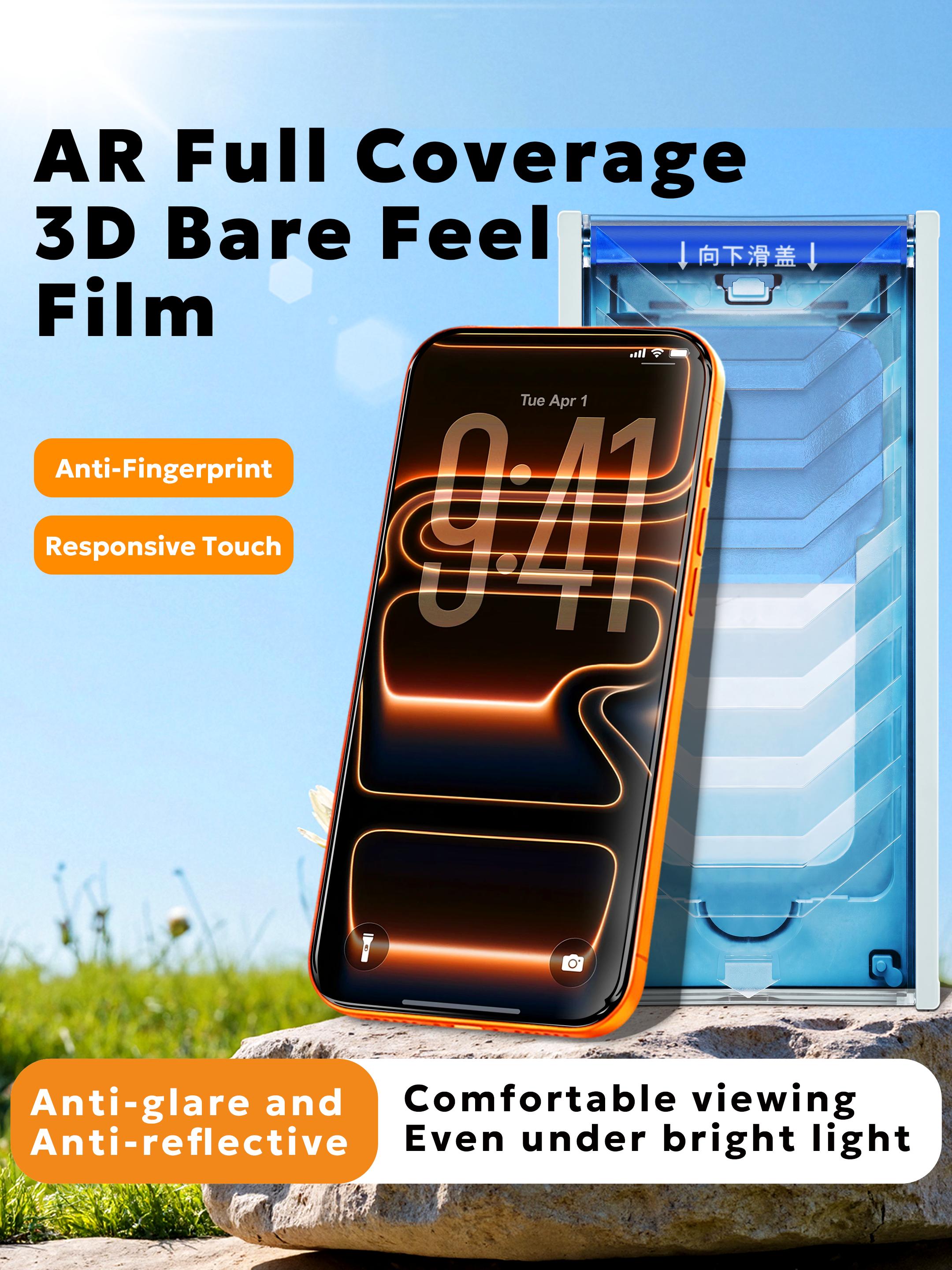
A technical guide to AR-coated screen films — thin-film interference physics, optical performance metrics, 3D hot-bending coverage, durability testing, and B2B sourcing criteria
Every glass surface reflects light. A bare display cover reflects roughly 4–8% of the light that reaches it, and that reflected light is what produces the mirror-like sheen that washes out a phone screen in direct sunlight. An anti-reflection film attacks this problem at the optical level: instead of scattering the reflection away as a matte finish does, it engineers the reflection out of existence through destructive interference inside a sub-micron coating stack. The result is a surface that stays legible in bright light while maintaining full clarity and color fidelity. This article explains how AR coating works, how it differs from anti-glare and standard clear films, what the key optical specifications actually mean, and how B2B buyers should evaluate and source AR films in 2026.
1. What Is an Anti-Reflection Film?
An anti-reflection (AR) film is an optical film that suppresses surface reflection by applying a thin-film interference coating — usually a stack of alternating high- and low-refractive-index dielectric layers — to a transparent substrate. The coating is generally a few hundred nanometres thick, far thinner than a human hair, and it works entirely by controlling how light waves interfere with one another at each layer interface.
AR coatings have been used for decades in camera lenses, eyeglasses, microscope optics, solar panels, architectural glass, and automotive head-up displays. In consumer electronics, the same technology has now migrated to display protection: an AR film is laminated over a smartphone, tablet, or instrument screen to reduce reflection and improve readability without sacrificing transparency.
| Model | AR-019 |
| Material | Glass film |
| Thickness | 0.26 mm |
| Surface Hardness | 9H |
| Light Transmittance | 95% |
| Reflection Rate | 0.6% |
| Edge Process | 3D hot bending |
| Application | iPhone 17 series |
| Key Characteristics | High transparency, anti-glare, scratch resistant, low reflection, full-screen coverage |
The headline figure here is 0.6% reflection rate against roughly 4–8% for uncoated glass. In practical terms, that is the difference between a screen that behaves like a dark mirror under office lighting and one that stays readable — a distinction that matters enormously for outdoor field devices, automotive infotainment, industrial HMI panels, and anyone who has ever tried to read a phone on a sunny day.
2. AR vs AG vs Clear Film: Three Different Optical Strategies
The three surface treatments most often confused with one another solve the glare problem in fundamentally different ways, and the differences show up directly in measurable optical performance. Choosing between them is a specification decision, not a marketing preference.
| Parameter | AR (Anti-Reflection) | AG (Anti-Glare / Matte) | Standard Clear Film |
|---|---|---|---|
| Working principle | Thin-film interference cancels reflected light | Surface roughness scatters glare in all directions | No optical treatment |
| Reflection rate | 0.5–1.0% | 2–4% (scattered) | 4–8% |
| Light transmittance | 94–96% | 88–92% | 91–92% |
| Haze | < 0.5% | 5–15% | < 0.3% |
| Image sharpness | Excellent — no scatter | Slightly softened by scatter | Excellent |
| Colour fidelity | High (ΔE < 1.0 achievable) | Slight milkiness | High |
| Best for | Outdoor readability, HDR displays, colour-critical work | Heavy overhead lighting, finger-glare reduction | Baseline protection, lowest cost |
| Typical cost index | High | Medium | Low |
The critical insight is that AR and AG are not competing versions of the same thing. AG reduces the intensity of glare by spreading it over a wider area, but the light is still there and the surface still looks hazy. AR removes the reflection itself, so both glare and the mirror effect disappear while the underlying image stays razor sharp. For devices where display quality is a selling point, AR is the technically correct choice; AG remains a reasonable compromise where diffuse, non-directional reflections dominate.
3. The Physics of AR Coating: How Thin-Film Interference Works
To specify an AR film intelligently, it helps to understand why the coating works at all. When light strikes the boundary between two media with different refractive indices, part of it reflects. For a single air-to-glass interface, the fraction reflected at normal incidence is given by the Fresnel relation R = ((n₁ − n₂) / (n₁ + n₂))². With air (n₁ ≈ 1.00) and typical cover glass (n₂ ≈ 1.52), that works out to roughly 4.3% per surface — and a display assembly with two surfaces reflects close to 8% of incident light.
3.1 The Quarter-Wave Condition
Now coat that glass with a thin transparent film of refractive index n and physical thickness d. Light now reflects twice: once at the air–film interface, once at the film–glass interface. If the film's optical thickness satisfies the quarter-wave condition — n·d = λ/4 — the second reflection travels an extra half-wavelength and arrives exactly out of phase with the first. The two reflected waves cancel by destructive interference, and the reflection essentially vanishes at that wavelength.
A single quarter-wave layer of magnesium fluoride (MgF₂, n ≈ 1.38) — the classic single-layer AR coating — drops glass reflection from about 4% to roughly 1.3%. That is already a visible improvement, but it only works well near one wavelength, which is why single-layer coatings leave a residual purple or green tint across the visible spectrum.
3.2 Multilayer Stacks for Broadband Performance
To suppress reflection across the entire 400–700 nm visible band, manufacturers build multilayer stacks of alternating high- and low-index materials. Each pair of layers adds another cancellation condition, and a well-designed 4–8 layer stack can bring average reflection below 0.5% while keeping residual colour shift (ΔE) under 1.0.
| Material | Refractive Index (n, 550nm) | Role in Stack | Deposition Method |
|---|---|---|---|
| MgF₂ | ~1.38 | Low-index layer | Thermal evaporation / sputtering |
| SiO₂ | ~1.46 | Low-index layer (most common) | Magnetron sputtering |
| Al₂O₃ | ~1.77 | Medium-index layer | Sputtering |
| ZrO₂ | ~2.10 | High-index layer | Sputtering |
| TiO₂ | ~2.40 | High-index layer | Sputtering / ion-assisted |
| Nb₂O₅ | ~2.35 | High-index layer (high durability) | Magnetron sputtering |
Why layer count matters: A 2-layer stack optimizes around a single target wavelength; a 4-layer stack broadens coverage across most of the visible spectrum; a 6–8 layer stack achieves broadband neutrality in the 400–700 nm range with minimal colour shift. Beyond roughly 8 layers, marginal optical gains no longer justify the added deposition cost and the elevated risk of interlayer adhesion or stress-induced cracking.
4. Anatomy of an AR Film: Layer-by-Layer Construction
A finished AR screen film is a multi-layer laminate, typically six to eight functional layers bonded into a total thickness measured in fractions of a millimetre. Each layer has a distinct job, and swapping or omitting any one of them changes the product's real-world performance far more than the headline optical specs suggest.
| 1. AF / Oleophobic Coating | Repels fingerprints, oil and water; raises water contact angle above 110° |
| 2. AR Coating Stack | 4–8 alternating high/low-index dielectric layers; the optical core of the product |
| 3. Hard Coat | Scratch-resistant layer protecting the coating stack; contributes to the 9H surface rating |
| 4. Substrate | Chemically strengthened glass (e.g. 0.26 mm) or optical-grade PET |
| 5. Adhesive Layer | Optically clear adhesive (OCA) or silicone-based adhesive; determines reworkability |
| 6. Release Liner | Protective carrier film removed at installation |
A critical specification detail: the difference between a glass-based AR film and a PET-based AR film. PET films are flexible, cheaper, and can be applied to flat or gently curved surfaces, but they cannot match the rigidity, surface hardness, or optical flatness of a glass substrate. The AR-019 uses a 0.26 mm glass film, which is why it can carry a 9H surface rating — a figure PET films generally cannot reach.
5. Key Optical and Mechanical Performance Metrics
When comparing AR film datasheets, these are the numbers that actually determine end-user experience. Each should be measured to a recognised standard, not quoted from a nominal design target.
| Metric | Typical AR Range | What It Means for the Buyer |
|---|---|---|
| Luminous transmittance | 94–96% | Higher = brighter image, less backlight power needed |
| Reflectance | 0.5–1.0% | Lower = less glare and mirror effect |
| Haze | < 0.5% | Lower = sharper image, no milky cast |
| Colour shift (ΔE) | < 1.0 | Lower = no visible tint or iridescence |
| Surface hardness | 9H (ASTM D3363) | Resistance to daily scratch contact |
| Coating adhesion | 5B (ASTM D3359) | Coating will not flake or peel in service |
| Water contact angle | > 110° | Fingerprint and smudge resistance |
| Total thickness | 0.20–0.33 mm | Affects touch sensitivity and device fit |
6. 3D Hot Bending: Achieving True Full-Screen Coverage
Modern flagship displays do not have flat edges. Their cover glass curves downward at all four sides, which means a flat protective film cannot physically conform to the display without leaving an unsightly air gap — the halo or rainbow ring familiar to anyone who has applied a flat protector to a curved phone.
The solution is 3D hot bending. The glass film is placed over a shaped graphite or ceramic mould and heated to roughly 650–750°C, at which point the glass softens enough to take the mould's curvature without losing its optical flatness in the central display region. After forming, the part is chemically strengthened and coated. The result is a film whose edges match the device's curvature within tight tolerances, eliminating edge lift and delivering genuine full-screen coverage — the process used in our AR-019 and, for a different optical strategy, in the anti-shatter film.
| Forming temperature | 650–750°C, tuned to the glass composition |
| Edge curvature radius | Matched to the target device's display edge geometry |
| Dimensional tolerance | Edge profile controlled to ±0.05 mm for consistent fit |
| Flatness in active area | Optical flatness retained across the display viewing zone |
| Post-forming treatment | Chemical strengthening, then AR and AF coating |
7. Manufacturing Process: From Substrate to Finished AR Film
AR film production is a precision coating operation. The coating layers are measured in nanometres, and a variation of even a few nanometres in layer thickness shifts the wavelength at which cancellation occurs — producing the purple, green or blue tint that betrays a poorly controlled process. The full sequence runs as follows:
8. Durability and Reliability Testing
Optical performance is only half the story. An AR film that delivers 95% transmittance on day one but loses its coating after three months of pocket use is a warranty liability. The following test battery is what separates a production-grade AR film from a laboratory prototype.
| Test | Method / Standard | Acceptance Criterion |
|---|---|---|
| Pencil hardness | ASTM D3363 | 9H, no visible scratch |
| Coating adhesion | Cross-hatch, ASTM D3359 | 5B — no coating removal |
| Abrasion resistance | Taber abraser / steel wool | No functional degradation of transmittance |
| AF coating durability | Reciprocating wipe cycles | Contact angle > 100° after 3,000+ cycles |
| Chemical resistance | Sunscreen, hand sanitiser, synthetic sweat | No coating damage after 24h exposure |
| UV ageing | ASTM G155, 500 h | ΔE < 2.0; no yellowing |
| Damp heat | 85°C / 85% RH, 240 h | No delamination or haze increase |
| Thermal shock | −40°C ↔ +85°C, 50 cycles | No cracking or layer separation |
| Optical re-verification | Spectrophotometry before / after ageing | Transmittance and reflectance within spec |
9. Where AR Film Delivers the Most Value
The primary application. Outdoor readability, HDR content fidelity, and reduced eye strain under bright ambient light. High-transmittance AR also lets the display run at lower peak brightness, saving battery.
Instrument clusters and head-up displays face strong, directional sunlight. AR coating is essential to keep readouts legible without washing out — and unlike AG, it does not blur fine graphics.
Control panels in factories, outdoor ticketing machines and field instruments operate under harsh lighting. AR film improves operator accuracy and reduces misreads on critical controls.
Colour-critical imaging and diagnostic displays benefit from AR's low colour shift and high clarity — the two properties matte finishes sacrifice most.
For brands assembling a full screen-protection range, AR film typically sits alongside standard high-definition tempered glass, privacy and blue-light blocking variants — each serving a different user requirement. See the full range in our product center.
10. B2B Sourcing Checklist for AR Films
Because AR performance depends on sub-micron coating quality, sourcing decisions should be driven by verified data rather than catalogue copy. Use the following checklist when evaluating a supplier.
| Item to Verify | Why It Matters |
|---|---|
| Measured transmittance & reflectance | Ask for spectrophotometer data, not nominal design values |
| Haze and colour shift (ΔE) | Reveals whether clarity is compromised for reflection reduction |
| Substrate type & thickness | Glass vs PET; determines hardness ceiling and fit |
| Edge process | 2.5D vs 3D hot bending; 3D required for curved displays |
| Coating layer count & materials | Indicates broadband capability and colour neutrality |
| Adhesive system | OCA vs silicone; affects reworkability and bubble behaviour |
| Test reports | Adhesion, abrasion, damp heat, UV ageing — dated and sample-traceable |
| RoHS / REACH compliance | Mandatory for EU and many other markets |
| MOQ, lead time & device list | Confirm the exact device models covered before committing |
| Packaging & installation kit | Dust-free application accessories reduce end-user complaint rates |
11. Frequently Asked Questions
Q: Is an anti-reflection film the same as a tempered glass screen protector?
Not necessarily, though they can be combined. A tempered glass protector is defined by its impact resistance and hardness; an AR film is defined by its optical coating. Many premium products are both — a chemically strengthened glass substrate carrying an AR coating and a 9H hard surface, as in the AR-019. The distinction matters when specifying: if impact protection is the priority, check drop and shatter performance; if readability is the priority, check transmittance, reflectance and haze.
Q: Does AR coating reduce a screen's brightness?
The opposite. By suppressing reflected light, more of the display's emitted light reaches the viewer's eye. An AR film with 95% transmittance makes the image appear brighter and more contrast-rich than an untreated surface, which is one reason device makers can reduce peak backlight and save power while maintaining perceived brightness.
Q: How is AR different from an anti-glare (matte) finish?
Anti-glare fights reflection by scattering it across a rough surface, which reduces the intensity of any single reflection but adds haze and softens the image. AR removes the reflection through interference, so glare disappears without haze — clarity and colour fidelity are preserved. If you have ever seen a matte screen protector look slightly milky or grainy, that is the haze cost of AG.
Q: Can AR film be applied to curved-edge displays?
Yes, provided the film is 3D hot bent to match the display's edge curvature. A flat AR film applied to a curved-display phone will lift at the edges and create the halo effect. 3D hot bending forms the glass over a mould at 650–750°C so that the finished film follows the device's contour, enabling genuine full-screen coverage.
Q: How do I verify a claimed 95% transmittance and 0.6% reflection rate?
Request spectrophotometer measurement data across the 400–700 nm band rather than a single-number claim. A genuine broadband AR film shows a consistently flat, low reflectance curve; a poorly engineered one shows deep dips at one or two wavelengths and elevated reflection elsewhere, which is what produces visible tinting. Also ask for post-ageing measurements to confirm the figures hold after damp heat and UV exposure. Our engineering team can supply measurement data and physical samples on request — see our contact page.
At TenWinGlass, we develop and manufacture AR-coated glass films with measured transmittance up to 95% and reflection rates as low as 0.6%, combined with 3D hot bending for full-screen coverage. From optical specification and sample validation through pilot runs and mass production, our engineering team supports the full development cycle from our ISO-certified facility in the Pearl River Delta manufacturing cluster.
Backed by 15+ years of precision optical coating and glass processing · Serving OEM/ODM brands across 30+ countries · Latest news & technical articles